Power Converter Circuit Diagram Circuit Converter Power Diag
Converter circuit developed technological How to build a power inverter circuit Search results for: circuits-diy.com
Dc Dc Power Converter Circuit Diagram
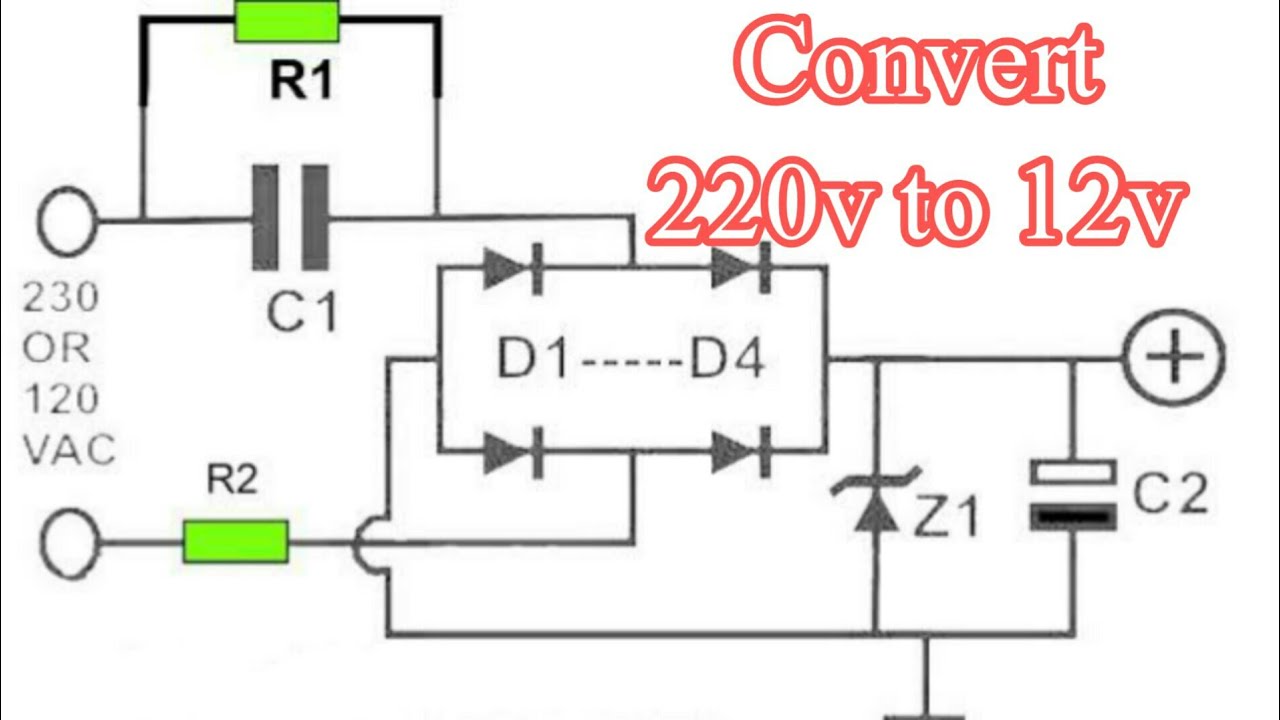
Eeetricks.blogspot.com: 230v ac to 5v dc converter circuit diagram Pin by arturo gambino on electronics Schematic diagram of the power converter circuit used in the developed
Boost converter power high circuit diagram gadgetronicx circuits step voltage diy
12 to 24 volt dc converter circuitsConverter inverter eleccircuit cd4047 220vac 12v voltage 220v schematics 12vdc Circuit analog converter digital simple schematic diagram using parts components layout pcb projects clock fig eleccircuitAnalog to digital converter circuit.
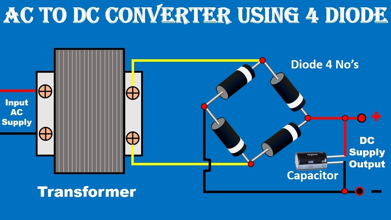
Dc to ac converter circuit projects on eleccircuit.comDc dc power converter circuit diagram 220/230v ac to 12v/5v dc regulated power dc converter bridge rectifierSimple power converter circuit diagram.

Ac current supply battery at heather belisle blog
Power circuit diagram of the proposed converter.Dc converter circuit diagram step using boost 12v 24v simple 12vdc 24vdc volt voltage 24 power circuits ic output wiring Rv inverter wiring diagram (rv electricity explained)Circuit converter power diagram seekic.
Frequency converter voltage circuit using ca3130 figure volts eleccircuit inputHigh voltage converter circuit Power converter circuit with rl load.What is 3 phase converter? types, working & circuit diagram.
Ac to ac converter circuit diagram
Power circuit diagram of the converterCircuit diagram and control system of the power converter: (a) overall Diagram converter circuit power simple dc should gr next diagrams multivibratorPower_converter.
Schematic converter developed technological230v dc ac circuit converter 5v diagram High power boost converter circuit diagramConverter overall axis.

Power-saving intermittent converter circuit diagram
Illustrative schematic of the power converter components that are9 volt power supply circuit diagram Schematic diagram of the power converter circuit used in the developedCircuit diagram of the power converter.
8: circuit diagram of the power converterVoltage to frequency converter circuit using ca3130 Converter diagram circuit intermittent saving power period voltage build labWiring diagram inverter rv electrical power diagrams camper magnum newmar system panel trailer hubs fuse typical inverters board charger wire.

(a) power circuit diagram of the proposed converter (b) characteristic
Power circuit diagram of the proposed converter.Power converter schematic The power converter circuit.Converter wiring daigram.
Ac to dc converter circuit daigramGeneralised power circuit diagram of the proposed converter Inverter circuit power electronics simple electrical transformer electronic board build shown schematics below amplifier breadboard above choose.


What is 3 Phase Converter? Types, Working & Circuit Diagram

Ac To Ac Converter Circuit Diagram

Schematic diagram of the power converter circuit used in the developed

RV Inverter Wiring Diagram (RV Electricity Explained) - RVing Beginner

Search results for: circuits-diy.com | VYCONVERT
Dc Dc Power Converter Circuit Diagram

Power-Saving Intermittent Converter Circuit Diagram | Circuits Diagram Lab