Power Splitter Circuit Diagram Single-core Power Splitters
Split wall piping diagram. Power supply splitter circuit Schematic splitter
Control Voltage Splitter Schematic
Split piping hvac refrigeration wiring inverter Splitter transformer splitters combiner matching Understanding power splitters
6m power splitters
Splitter splitters uncompensatedSplitter circuit rf electronics transformer jp Divider wilkinson circuit 50mhz splittersCircuit breaker control schematic explained.
Splitter / it’s fun to build electronics circuits.|feb.2019Splitter circuit power supply op amp using diagram current eleccircuit suitable voltage powers regulated load ground has Poe rj45 ethernet pinout circuit schematic utp basic adaptador paso instructables hackerspace elab přečíst zdroj článkuSchematic structure of 1×2 power splitter.

Control voltage splitter schematic
Splitter 5v voltage convertVoltage divider circuit explained! Circuit diagram for the standard splitter. the control module containsSplitter circuit.
Battery splitter micropower circuit seekic voltage gr next circuitsSchematic diagram of circuit breaker opening and closing Voltage divider circuit explainedPower divider和power splitter怎么区分?-edn 电子技术设计.

A schematic diagram of the 1×8 optical power splitter with an enlarged
Rf power splitter circuit diagramRf power splitter circuit diagram Basic resistive power splitter.Voltage splitter transistor amplifier totem opamp eleccircuit converter sensing operational.
Power supply splitterCurrent splitter circuit. Splitter schematic power splitters dual core transformer basicPower supply splitter circuit using op-amp.

Power splitter result
Micropower_battery_splitterSchematic of the parallel power splitter Breaker switch interconnection closing naderCircuit diagram for the standard splitter. the control module contains.
The schematic drawing of the 3-db power splitter. the final dimensionsSingle-core power splitters Splitter guitar way circuit active seekic diagram supply powerSplitter splitters combiners frequently circuits lumped isolation combiner internal.

Rf power splitter circuit diagram
Power over ethernet (poe) adapter – elabSplitter resistive Frequently asked questions about power splitters/combinersGeometry of the power splitter..
Understanding power splittersSplitter enlarged Dual-core power splitters4-way active guitar splitter.

The modified power splitter: (a) schematic of the modified power
Power supply splitter circuit using op-ampWhat are the functions of power splitter? Splitter splittersBreaker wiring schematic abb vcb mccb motorized explained voltage scheme breakers schematics 11kv typical circuits mpcb dhp components switches.
.


What are the functions of power splitter?

Power Over Ethernet (PoE) Adapter – eLab | hackerspace | Ethernet
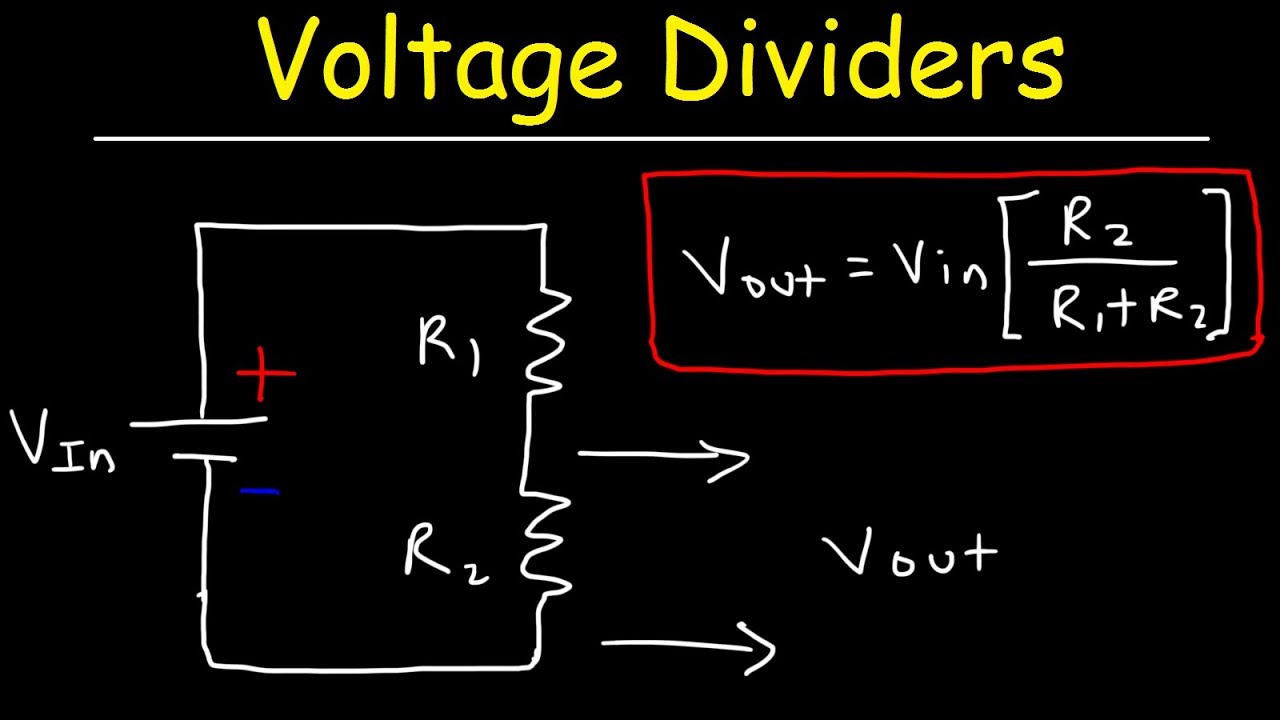
Voltage Divider Circuit Explained! - YouTube

Control Voltage Splitter Schematic

Understanding Power Splitters | Mini-Circuits Blog

4-Way Active Guitar Splitter - Power_Supply_Circuit - Circuit Diagram